Rectifying Raster Data
Georeferencing also known as Rectification is a process of defining the real world location of a set of data. In GIS, when data from different sources need to be combined and then used, it is important to have a common referencing system.
This is used in both vector and raster GIS data. Reference information can come from several sources such an existing reference map, GPS readings, etc; this commonly referred to as Ground Control Point or GCP. Most georeferencing tasks are undertaken either because the user wants to produce a new map or because they want to link two or more different datasets together by virtue of the fact that they relate to the same geographic locations.
We will use the Georeferencer Plugin in QGIS to reference rasters to geographic or projected coordinate systems by creating a new raster.
Creating a new project
1. Open QGIS and create a new project. In the menu, select
File ‣  New Project.
2. Open Project Properties and click the Coordinate Reference System (CRS) tab. Set the following options.
- Check the Enable ‘on-the-fly’ CRS Transformation.
- In the Coordinate Reference System, choose Luzon 1911 or EPSG:4253.
Loading Vector data
1. Open your roads.shp vector. Improve the symbology of the road vector. The road layer in the main Map Canvass will be used to get the georeferenced points.
Georeferencing images
Load the unreferenced image
1. Load the Georeferencer plugin, click Plugins ‣ Georeferencer ‣ Georeferencer.
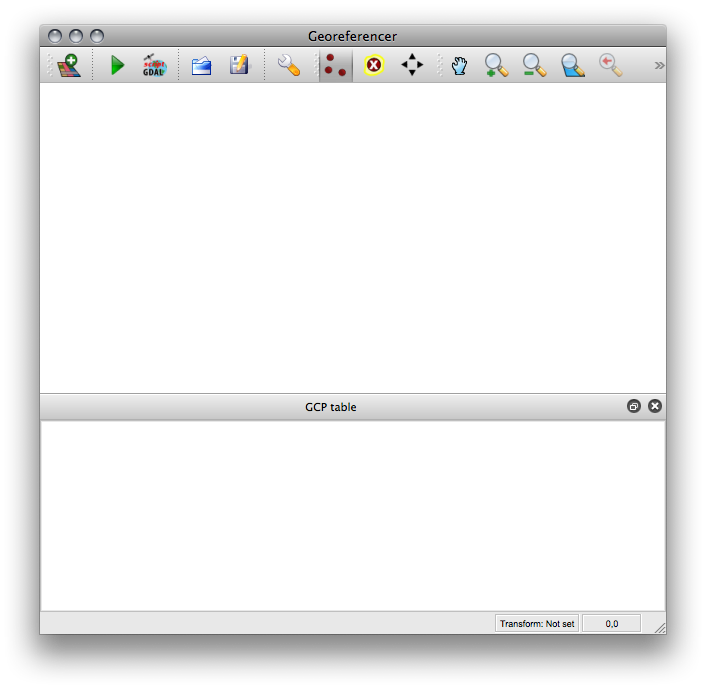
2. Load the image file that will be rectified. Within the Georeferencer
window, click  Open Raster the image map.
Select the nb51-7.jpg, click OK.
Open Raster the image map.
Select the nb51-7.jpg, click OK.
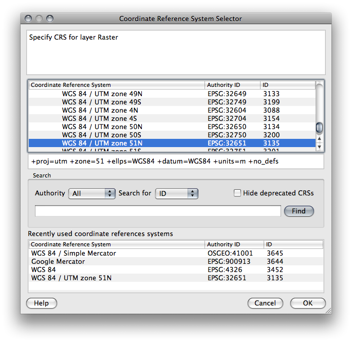
3. A new window will appear for the CRS of the raster layer, select Luzon 1911 or EPSG:4253, click OK.
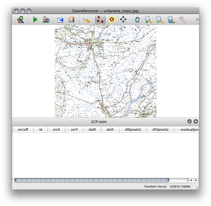
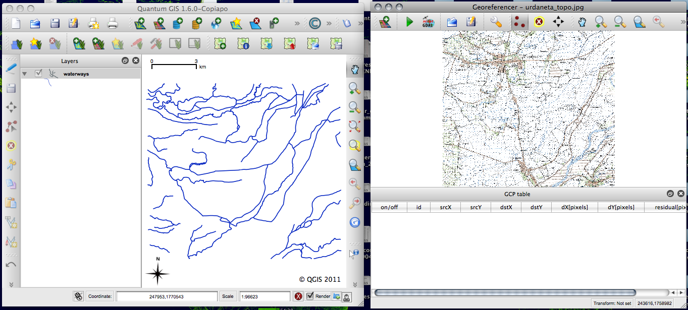
The raster will show up in the main working area of the dialog. Once the raster is loaded, we can start to enter reference points.
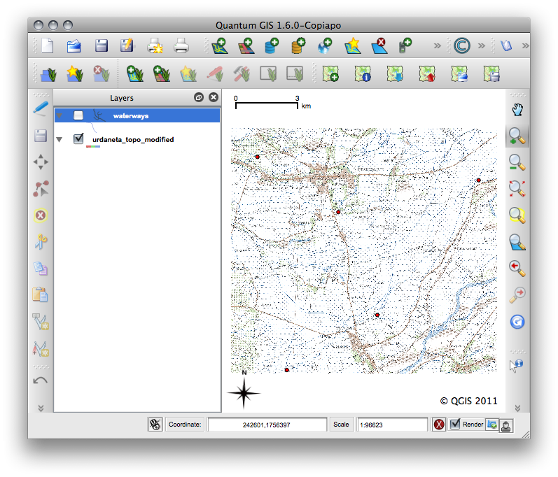
4. Adjust the size and location of both the georeferencer window and the main QGIS map view. Similar to the image below:
Add control points
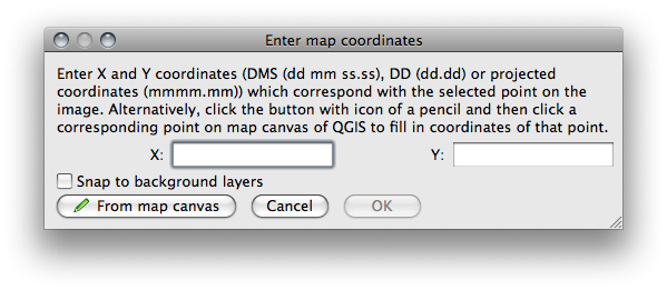
1. Using the  Add Point button, add a point to
the main working area. Click on a point in the raster image and click the
button From map canvas to add the X and Y coordinates with the help
of a georeferenced map already loaded in the QGIS map canvas. Use the zoom and
pan to navigate around the map in the Georeferencer and main Map Canvass.
Add Point button, add a point to
the main working area. Click on a point in the raster image and click the
button From map canvas to add the X and Y coordinates with the help
of a georeferenced map already loaded in the QGIS map canvas. Use the zoom and
pan to navigate around the map in the Georeferencer and main Map Canvass.
Tip
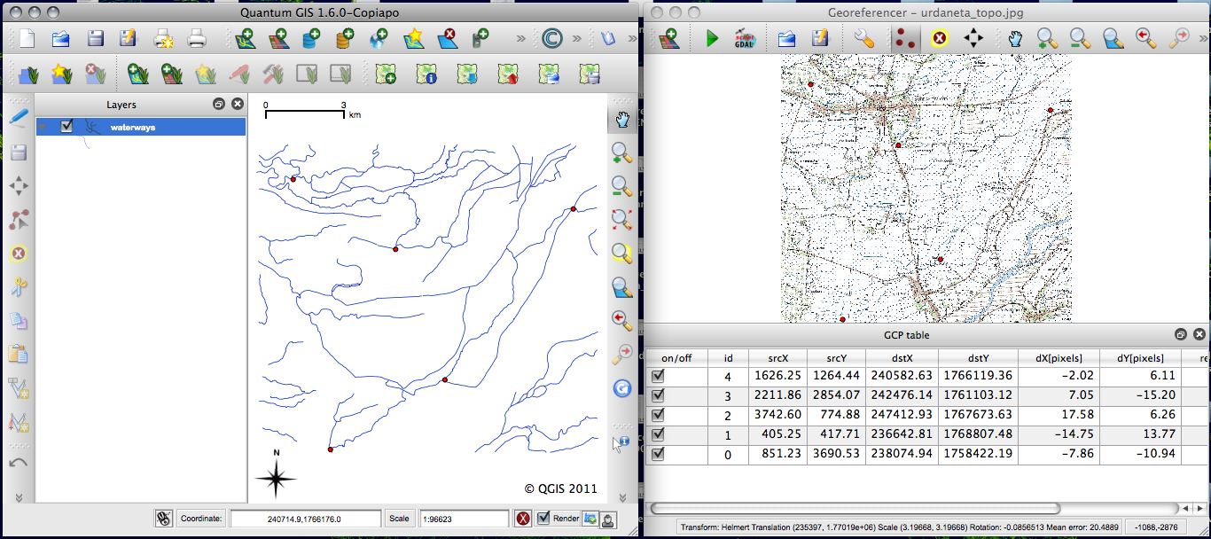
When selecting GCPs, it is best to choose points from across the image, balancing the distribution as much as possible; this will increase the positional accuracy. Since we are using the river data in this exercise, it is best to use river junctions as your GCPs.
2. Continue entering points. You should have at least 4 points, and the more coordinates you can provide, the better the result will be. There are additional tools on the plugin dialog to zoom and pan the working area in order to locate a relevant set of GCP points.
Note
The points that are added to the map will be stored in a separate text file (filename.points) usually together with the raster image. This allows us to reopen the Georeferencer plugin at a later date and add new points or delete existing ones to optimize the result. The points file contains values of the form: mapX, mapY, pixelX, pixelY.
You can use the Load GCP Points and Save GCP Points buttons to manage the files. Within the GCP table you can click on a column header and therewith enable e.g. numerical sorting. The GCP list is automatically updated.
Defining the transformation settings
After completing the selection of GCPs, we will define the transformation settings for the georeferencing process. Various options are available and the determination of the appropriate settings will depend on the source of input data, number of GCPs and the ultimate objective of the exercise.
- Transformation type - Depending on how many ground control point you have captured, you may want to use different transformation 9algorithms. Choice of transformation algorithm is also dependent on the type and quality of input data and the amount of geometric distortion that you are willing to introduce to final result.
- Resampling method - this is the process of geometrically transforming digital images. Different resampling methods can provide varying degree of “image” quality of the output.
- Compression - for very large images, you can define a compression option to reduce the file size.
- Target resolution - the pixel resolution of the output raster.
1. To define the transformation settings, click  Transformation settings. In the
Transformation setting
window, select the following options:
Transformation settings. In the
Transformation setting
window, select the following options:
Transformation type - Helmert
Resampling method - Nearest neighbhor
Compression - LZW
Target resolution - keep it unchecked.
Output raster - nb51-7_modified
Target SRS - Luzon 1911

You can optionally generate a pdf map and also a pdf report. The report includes information about the used transformation parameters. An image of the residuals and a list with all GCPs and their RMS errors.
Starting the georeferencing
1. After all GCPs have been collected and all transformation settings are defined, just press the button Start georeferencing to create the new georeferenced raster.
2. The georeferenced image should be loaded into your map canvass. If the output raster is mis-aligned, You can adjust the GCPs and re-run the process.